Wire
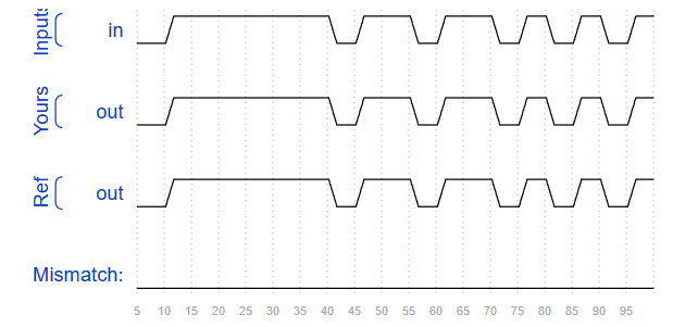
创建一个具有一个输入和一个输出的模块,其行为类似于导线。与物理线不同,Verilog中的线(和其他信号)是定向的。这意味着信息只在一个方向上流动,从(通常是一个)源流向接收器(源也经常被称为驱动程序,它将值驱动到线路上)。在Verilog的“连续赋值”()中,右侧信号的值被驱动到左侧的导线上。赋值是“连续的”,因为即使右边的值发生了变化,赋值也会一直持续下去。连续的任务不是一次性的。
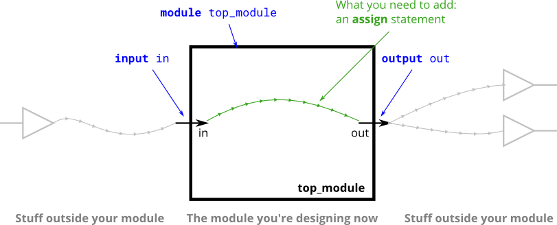
module top_module( input in, output out );
    assign out = in;

endmodule

endmodule
仿真图片:
Wire4
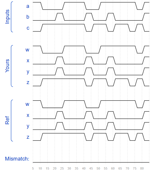
创建一个具有 3 个输入和 4 个输出的模块,其行为类似于建立这些连接的电线:
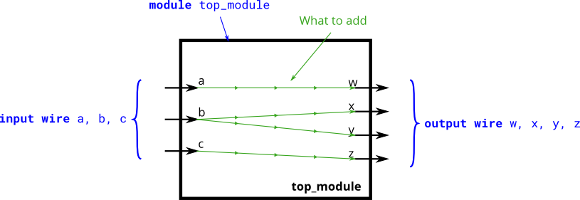
module top_module(
    input a,b,c,
    output w,x,y,z );
    assign w = a;
    assign x = b;
    assign y = b;
    assign z = c;

endmodule
仿真图片:
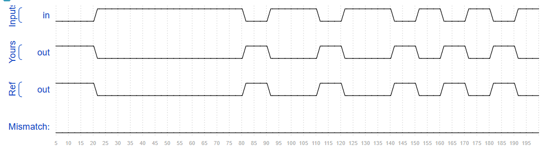
Notgate
创建一个实现非门的模块。

module top_module( input in, output out );

    assign out = ~in;

endmodule
仿真图片:
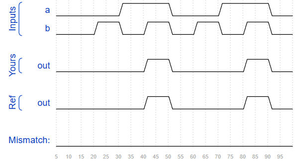
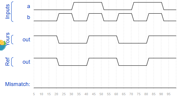
Andgate
创建实现与门的模块。

module top_module(
    input a,
    input b,
    output out );

    assign out = a & b;

endmodule
仿真图片:
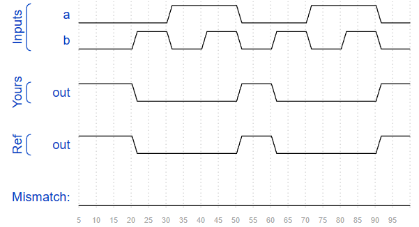
Norgate
创建实现或非门的模块。
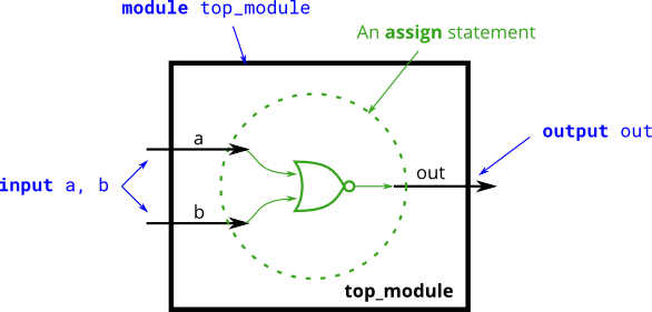
module top_module(
    input a,
    input b,
    output out );
    assign out = ~(a|b);

endmodule
仿真图片:
XNOR gate
创建一个实现同或门的模块。

module top_module(
    input a,
    input b,
    output out );
    assign out = a~^b;

endmodule
仿真图片:
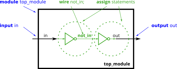
Declaring wire
当您需要使用连接时,您应该在模块体中声明它,在第一次使用它之前的某个地方。(将来,您将遇到更多类型的信号和变量,它们也以同样的方式声明,但现在,我们将从类型为wire的信号开始)。
module top_module(
input a,
input b,
input c,
input d,
output out,
output out_n );
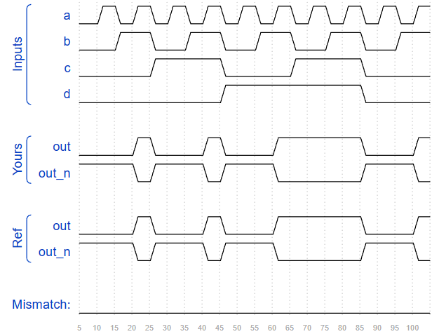
wire w1;
wire w2;
assign w1 = a&b;
assign w2 = c&d;
assign out = w1|w2;
assign out_n = ~out;
endmodule仿真图片:
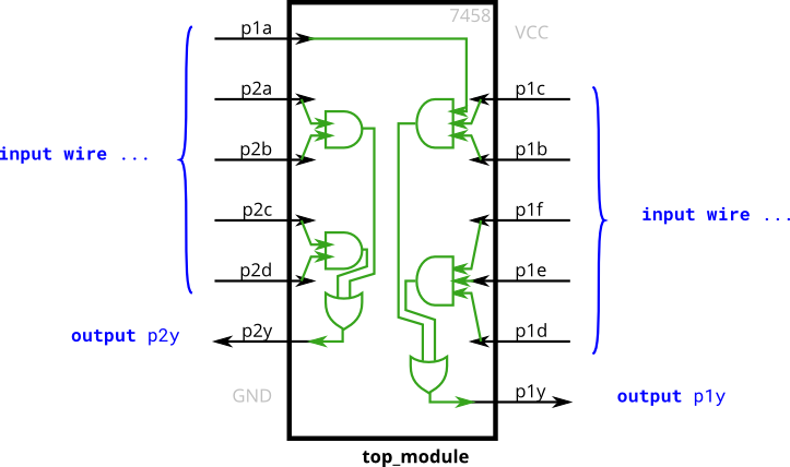
7458 chip
创建与 7458 芯片具有相同功能的模块。它有 10 个输入和 2 个输出。您可以选择使用语句来驱动每根输出导线,也可以选择声明四根导线用作中间信号,其中每根内部导线由其中一个与门的输出驱动。对于额外的练习,请尝试两种方式。
module top_module (
    input p1a, p1b, p1c, p1d, p1e, p1f,
    output p1y,
    input p2a, p2b, p2c, p2d,
    output p2y );
    assign p1y = (p1a & p1c & p1b) | (p1f & p1e & p1d);
    assign p2y = (p2a & p2b) | (p2c & p2d);

endmodule
仿真图片:
